1. Basic principle of VRL Battery
The VRL battery is based on the principle of electrochemical reaction. When charging, it converts electrical energy into chemical energy and stores it in the battery. When discharging, it converts chemical energy into electrical energy and supplies it to the external system.The charging and discharging process is completed by electrochemical reaction, as shown below:
2Pb十O2=2PbO
2PbO十2H2SO4=2PbS04+2H2O
The charge and discharge reaction of the lead-acid battery is shown in the first chemical reaction equation in the figure above.When the battery is charged, the positive electrode will release oxygen and the negative electrode will release hydrogen. The fully sufficient positive and negative electrodes are respectively lead dioxide (PbO2) and spongy lead (Pb).When the external circuit is connected, it reacts with sulfuric acid to produce lead sulfate and water.During charging, it is converted into lead dioxide (PbO2) spongy lead (Pb) under the action of oxidation and reduction potentials.The above equation describes the internal circulation of oxygen during the float charging process.
2. Battery Installation
2.1 Preparation
Detect the open circuit voltage of each battery one by one
2V Cell: U>2.06; 6V battery pack: U>6.18V; 12V battery pack:U>12.36V
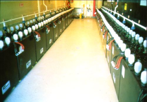
Check whether the battery rack is stable and level. For battery racks with 2 rows and 4 layers or 3 rows and 5 layers, the whole rack should be fixed on the building. When the battery is placed in a metal cabinet or on a rack, care must be taken to prevent the pole from contacting the surrounding metal parts or connections (safety distance: 10mm).Appropriate ventilation should be provided at the top and bottom of the cabinet and rack to allow the heat generated by the battery and charging system to dissipate. There must be a gap of at least 5mm between adjacent batteries. Do not use metal clips to connect the battery pack. A system structure made of insulating materials should be used. The relevant standards for the battery cabinet or the room where the corresponding equipment is installed are:IEC364-4,EV50091-1,IEC896-2。

2.2 Installation
The installation operation must use insulating tools to properly lubricate the inserts and connectors with silicone-based grease, and never use petroleum-based grease. Check the voltage of the entire battery pack: it should be the same as the number of batteries in series. After connection, tighten with a torque wrench. The torque setting is as follows:
M5 connect: 2.5±1 N
M6 connect: 2.5±1 N
M8 connect: 2.5±1 N
M12 connect: 2.5±1 N
3.Debugging
For floating charging applications, if the battery is only stored, assembled, and debugged for a period of time, the battery pack is connected to the charging system. Safety system: fuse, circuit breaker and battery isolation relay need to be tested separately. The first thing is to keep the battery floating for 4-5 days. This can make up for the capacity loss during battery storage and improve the uniformity between single cells (for 3 months storage at 20°C).

4.Running
4.1 Float charging mode
The characteristic of this mode of operation is to always provide power to the battery pack. Therefore, there is always a small amount of current supplied to the battery to maintain its full charge state in order to meet any (current) requirements at any time.
4.2 Float charge voltage and float charge current
The effective value of the AC component of the floating charge current should be
4.3 Charging Condition
The charging method is to charge the battery with a constant current of 0.1C-0.2C. When the charging voltage rises to the required voltage, it will be maintained for 12-15 hours or the charging current will be 0.001A/AH and maintained for 2-3 hours. Enter the floating state.
4.4Discharge Situation
The service life of a battery can be affected by too many continuous deep discharges. Because of this, the discharge termination voltage should be limited according to different discharge currents.
4.5The influence of temperature
The designed operating temperature range of the sealed battery is -15℃~+40℃. Below -15°C, there is a danger of freezing. However, it can also be used under lower temperature conditions, but some specific conditions are required. The use of sealed batteries under high temperature conditions affects their service life. When the temperature rises by 10°C, the life span is shortened by 1/2. The best operating temperature is 20°C. When it is higher than 40°C, there is a risk of thermal runaway.
4.6 Regular Checking
Periodic inspection is to ensure that the charging voltage, current setting value, discharge intensity, temperature, storage conditions and other conditions can meet the initial setting requirements of the operation. In addition, regular discharge can be used to evaluate the possible endurance ability to find signs of aging of the faulty single cell and the entire battery pack, so that the appropriate replacement time can be determined.
Reference:
Chen Wei.Operation, maintenance and troubleshooting of valve-regulated sealed lead-acid batteries for electric power[J]electrotechnics,2012(11)

